Prof. Dr. Ahmet Taner Kışlalı Mah. 2781. Sok. No: 5 Çankaya 06810 Ankara/Turkey
info@psengineeringservice.com
+90 312 240 84 86
Pipeline Geometry Inspection
General Information about the PS Engineering Caliper Tool System
Dents affect the efficient operation of a pipeline as they restrict the flow of the transported medium and tend to induce spot-like formations of sedimentation, turbulence, erosion, corrosion and hydrates. The pipeline's service life is shortened further by localized excessive mechanical stress.
Geometric deviations can be located and their dimensions determined by means of the PS Engineering Caliper Tool (PS-C) pipeline inspection tool. Its use now forms an integral part in the acceptance of new pipelines and the monitoring of pipelines in operation. The PS-C works during the normal operation of a pipeline and is propelled through the line by the transport medium.
Due to the long-standing experience and progressive improvements, the PS- C's purpose-adapted structure meets even extreme conditions for operation in pipelines. The PS-C is able to pass extreme deformations (up to 25 %) and, due to the high sensitivity of the gauging system and the large number of sensing fingers, even the smallest dents can be detected. Especially during the inspection run in crude oil pipelines, the polyurethane cup sleeves are designed for easy running.
The data collected during the inspection run is analyzed by means of the evaluation software that shows the graphical representation of the inner pipeline diameter. Normally girth welds, wall thickness changes, installations, etc. can be seen on the chart in addition to dents and ovalities. Time pulses at 1-second intervals indicate the speed of the PS-C inside the pipeline. Marker signals are shown on the chart in the form of signal bands. The marker position serves a fixed reference point for flaw detection.
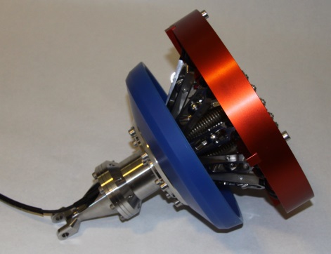
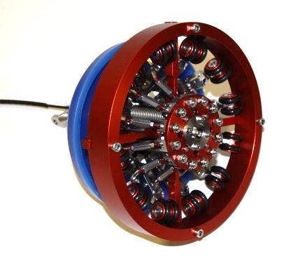
Design of the PS Engineering Caliper Tool (PS-C)
The PS Engineering Caliper Tool is an intelligent inspection system which serves to measure diameter reductions in pipelines - such as dents, ovalities, girth welds, wall thickness changes - and to detect T-pieces, valves and other installations.
The basic body is the central mechanical element of the PS-C. All other components are fixed to the basic body. The PS Engineering CaliperTool (PS-C) is designed for heavy duty work in the pipeline environment. All active components are manufactured out of stainless steel or aluminium to operate in crude oil, gas, air, saltwater (with inhibitors) and other products.
The cup sleeves fill the cross section of the pipeline and enable the PS-C to be transported through the pipeline by the medium. The pig runs on flexible polyurethane cups, able to negotiate extreme diameter reductions (risers), with excellent long run performance under all conditions.

Mechanical Measuring System
The mechanical measuring system is consisting of a circumferential array of spring-loaded sensor arms with sensor wheels.
While the sensor arms are spring-loaded the sensor wheels are pushed to the inner pipe wall of the pipeline.
This continuous and direct contact with the inner pipe wall with guarantee that any radial deflection of a sensor wheel, caused by a geometric deformation of the pipeline will be measured and recorded.
Odometer Wheels
The PS-C is equipped with at least two odometer wheels to increase reliability. The wheels are selfcleaning to eliminate skidding. The sealed roller bearing is self-lubricating and pressure-compensated to minimize friction and increase its reliability under all conditions.
Electronics
All movements of the sensing fingers (spider) are transferred to a linear potentiometer via the sensing rod. A fast single-channel analog digital converter transmits the data received to a process control computer. As a next step, all data received from the odometer wheels and the marker system are added, provided with a time marker and then stored in a flash memory. Upon completion of the pig run all data received are transferred to a personnel computer via a high-speed interface. To guarantee a maximum operating time (up to 700 hours), high-performance lithium batteries are used.
In order to guarantee the proper functioning of the electronics under all conditions, intensive tests are made; i. e. extreme temperature conditions are simulated in a climatic test cabin and vibrations are generated with an electromagnetic oscillation system.

All movements of the sensing fingers (spider) are transferred to a linear potentiometer via the sensing rod. A fast single-channel analog digital converter transmits the data received to a process control computer. As a next step, all data received from the odometer wheels and the marker system are added, provided with a time marker and then stored in a flash memory. Upon completion of the pig run all data received are transferred to a personnel computer via a high-speed interface. To guarantee a maximum operating time (up to 700 hours), high-performance lithium batteries are used. In order to guarantee the proper functioning of the electronics under all conditions, intensive tests are made; i. e. extreme temperature conditions are simulated in a climatic test cabin and vibrations are generated with an electromagnetic oscillation system.
Chart
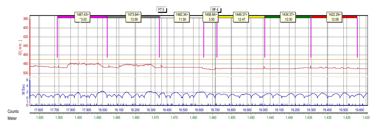
The chart shows the diameter profile of the pipeline. The results are easy to interpret and cannot be manipulated; furthermore, they are available immediately after the run.
Linear accuracy and registration of girth welds allow the recorded data to be related directly to the pipe welding books and other as-built records.
The PS-C sensing mechanism responds to minute changes in pipeline geometry: dents, ovalities, wall-thickness changes and girth welds are clearly indicated in the chart
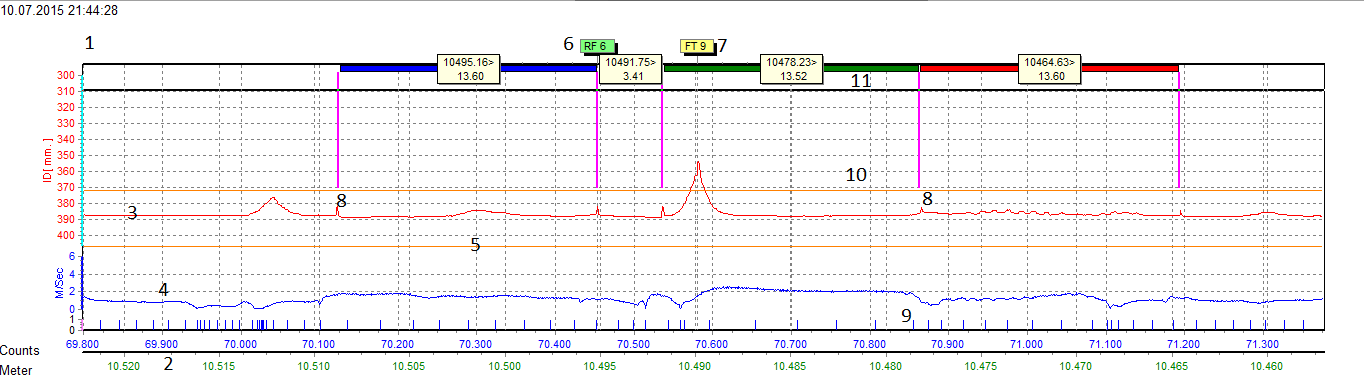
Analysis software showing an ovality with dent of 14.2 % of OD in a pipeline.
(1 - Pipeline ID, 2 - Distance, 3 - Recorded Data, 4 - Tool speed, 5 - Pipeline OD, 6 - Weld Reference point, 7 - Ovality with dent of 14.2 % of OD, 8 - Girth weld, 9 - Time marks, 10 – Pipeline reduction limit, 11 - Pipebook)
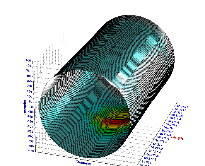
Resulting ovality with dent referenced to the PS-C data above.

Pipebook correction example
Calibration and Computation of ID Reduction
Prior to the inspection run, the tool was calibrated by using a calibration ring, which simulated dents and ovalities by small slabs of specified thickness. With the help of this calibration, the inspection data were correlated to dents, ovalities and other ID reductions. The following figure represents an example of the calibration of dents (ID reduction 2.5 to 100 mm) and ovalities (ID reduction 5 to 100 mm).
The evaluation program uses the calibration results to generate the Calibration Curve:

Feature Identification
The following examples show typical pipe features.
Girth Weld: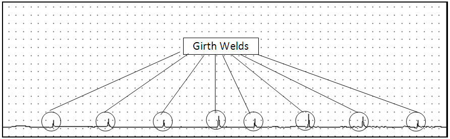
Dent: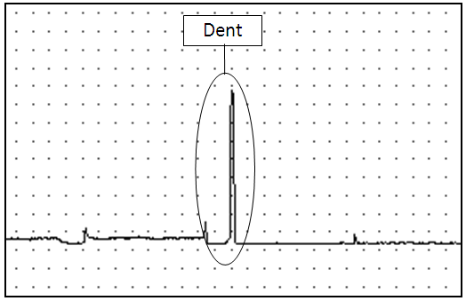
Wall Thickness Change: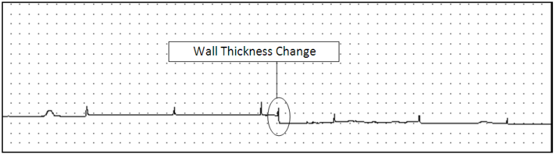
Ovality: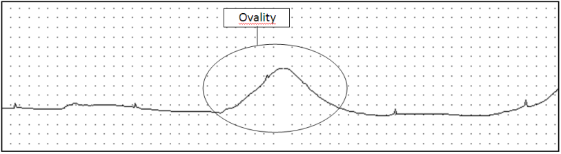
Valve Station: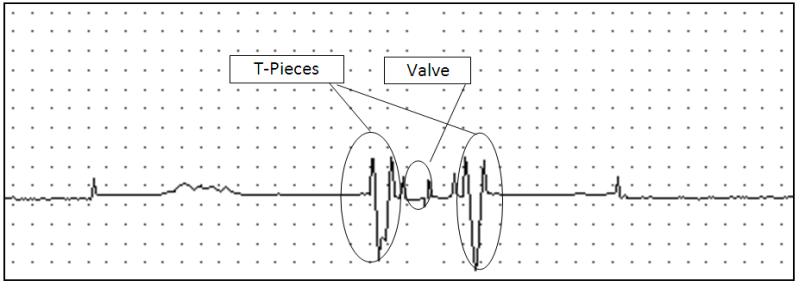
Ovality with Dent: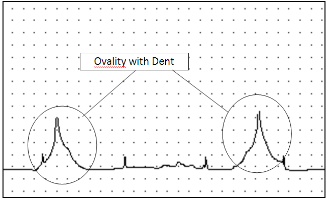
Technical Specification:
| Sizes available | from 8 Inch upwards |
| Overall length | approximately 1.8 x outer Diameter-D |
| Minimum passage | 75% of D |
| Accuracy of Distance information: | ≤ 0.2mm from ref. Girth Weld or 0.1% of total distance |
| Odometer: | 2 Odometer |
| Accuracy of Defect information: | Accuracy of Internal Dia. Changes +/- 0.1% Accuracy of Defect Measurement +/- 0.1% |
| Additional location information: | chart marker system |
| Location accuracy: | 0.1% between marker or by comparing girth welds with pipe welding books |
| Maximum pressure on housing: | 120 bar (higher pressure optional) |
| Maximum travelling distance: | >600 km in crude oil l>600 km in gas and water |
| Battery lifer: | 700 hours |
| Products: | all liquids and gases (acid gas and corrosive products on request)) |
| Minimum bend radius: | 1.5x D optional |
Caliper Tool Specifications
6” PS ENGINEERING CALIPER TOOL 8” PS ENGINEERING CALIPER TOOL 10” PS ENGINEERING CALIPER TOOL 12” PS ENGINEERING CALIPER TOOL 14” PS ENGINEERING CALIPER TOOL 16” PS ENGINEERING CALIPER TOOL 18” PS ENGINEERING CALIPER TOOL 20” PS ENGINEERING CALIPER TOOL 24” PS ENGINEERING CALIPER TOOL 30” PS ENGINEERING CALIPER TOOL 36” PS ENGINEERING CALIPER TOOL 40” PS ENGINEERING CALIPER TOOL 46” PS ENGINEERING CALIPER TOOL 48” PS ENGINEERING CALIPER TOOL 56” PS ENGINEERING CALIPER TOOL